4 Bit Adder Circuit Diagram
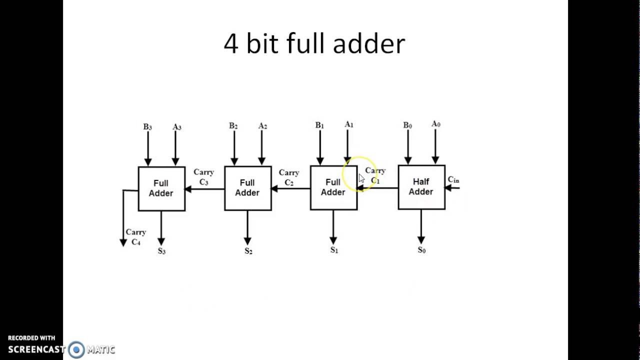
11+ 4 bit adder circuit diagram 😊 four bit parallel adder. 4 bit binary adder circuit / block diagram [diagram] logic diagram of 4 bit full adder
[DIAGRAM] 4 Bit Adder Circuit Diagram Waveform - MYDIAGRAM.ONLINE
[diagram] 4 bit adder logic diagram 4-bit adder circuit diagram 4 bit binary subtractor circuit diagram
Adder alu circuit given nor nand
Verilog subtractor4-bit binary adder-subtractor 11+ 4 bit adder circuit diagram4 bit adder circuit diagram.
Let's learn computing: 4 bit adder/subtractor circuitCircuit diagram for 4 bit binary adder using ic 7483 Combinational and sequential design of a 4-bit adder. (a) ha circuit🎉 4 bit parallel adder theory. 5.9: four. 2022-10-30.

4 bit adder circuit diagram
Download 4 bit adder circuit stick and logic diagram1 bit full adder circuit diagram 2 bit adder circuitMake adder subtractor bit carry verilog binary using ripple 4bit want subtraction addition operation output hdl has value which.
4-bit adder and subtractor circuit explained4-bit adder-subtractor in digital circuit [diagram] 4 bit adder circuit diagram waveformAdder subtractor bit circuit ripple carry diagram logic using project build only digital computing learn let its single indie electronics.

4 bit adder subtractor circuit diagram
4 bit binary adder circuit diagramDraw and explain 4 bit binary arithmetic or adder circuit diagram Adder bit parallel four circuit diagram binary subtractor logic digital full block example geeksforgeeks detailed discussionCircuit adder bit diagram logic computing learn let.
4 bit adder diagram2 bit adder circuit 4 bit adder pin diagramIncrémenteur binaire 4 bits – stacklima.

[diagram] logic diagram 4 bit adder
Adder bcd cheggcdn4 bit adder circuit diagram » wiring core Bcd adderLet's learn computing: 4 bit adder circuit.
8 bit full adder circuit diagramCircuitverse 4 bit binary adder subtractor with overflow detection .


![[DIAGRAM] 4 Bit Adder Circuit Diagram Waveform - MYDIAGRAM.ONLINE](https://i2.wp.com/www.researchgate.net/profile/Saman_Amarasinghe/publication/37595015/figure/download/fig7/AS:309873876193289@1450891097709/Full-Adder-Circuit-Diagram.png)


